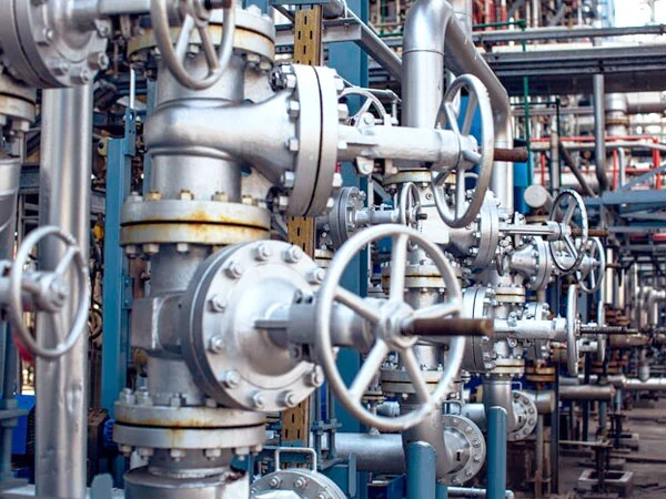
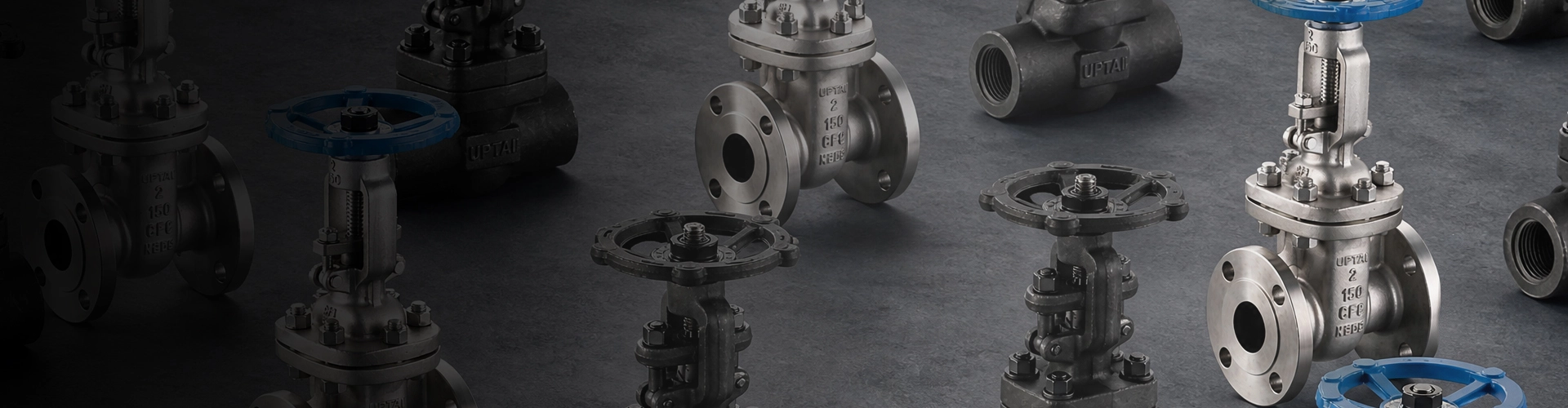
Gate Valves
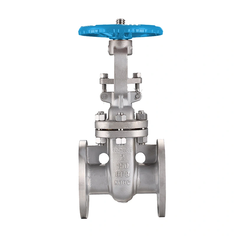
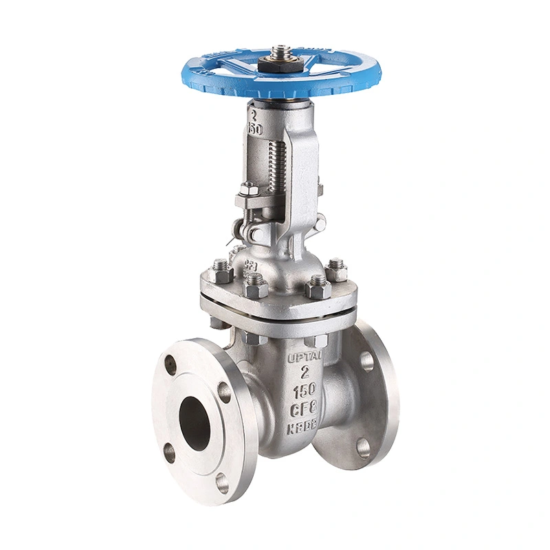
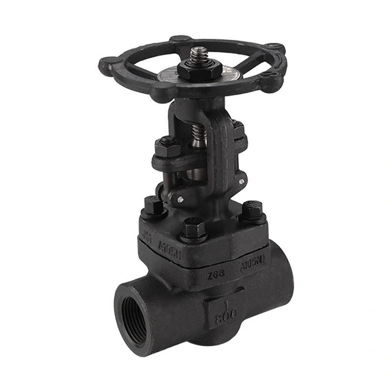
ANSI 150LB Stainless Steel Gate Valve
ANSI 150LB stainless steel gate valve designed in accordance with API 603 and ASME B16.34. It features RF flanged ends, Stellite 6 hard-faced seats and NACE requirements for industrial pipeline service, providing bi-directional shutoff and a straight-through flow path with low pressure loss.
The ANSI 150LB Stainless Steel Gate Valve is configured for pipeline isolation where a full-bore flow path and a stainless steel valve body are required. The gate moves vertically to open or close the passage, making this valve suitable for applications that normally require fully open or fully closed service rather than continuous throttling. The listed configuration covers NPS 2" to 48" and uses handwheel or gear operation according to valve size.
Shangtai manufactures industrial valves in Wenzhou, Zhejiang, China. Valve production includes material preparation, machining, component assembly, pressure testing, inspection, marking, and final packaging. Product configuration can be confirmed according to pipeline size, pressure class, operating medium, temperature, material requirements, connection standard, and applicable project specifications.
Main Dimensions
| Size | 2" - 48" |
| Pressure Class | CL150 |
| Design and manufacturing standards | ASME B16.34 / API 603 |
| Face-to-Face Dimensions Standard | ASME B16.10 |
| End Connections | RF-compatible flanges |
| Testing and inspection | API598 |
| Connection Standards | ASME B16.5 (NPS 2" ~ 24"), ASME B16.47 Series A (NPS 26" and up) |
| Pressure-Temperature Ratings | ASME B16.34 |
| NACE Standards | NACE MR0175 / ISO 15156 |
| Valve Operator | Handwheel (2" through 16"), Gear Operator (18" and above) |
| Maximum Working Pressure | 285 PSI |
| Temperature Range | -29°C ~ +120°C |
| Body Material | ASTM A351 CF8 / CF8M |
| Disc Material | ASTM A351 CF8 / CF8M |
| Stem Material | ASTM A182 F304 / F316 |
| Seat Material | ASTM A182 F304 / ASTM A351 CF8M + Stellite 6 |
| Options | Other materials are available upon request. |
Gate Valve Construction and Operating Principle
The valve uses a gate-type closure element that travels perpendicular to the pipeline flow direction. When the gate is fully raised, the flow passage is opened; when the gate is lowered, the passage is closed. This straight-through arrangement is commonly selected for pipeline isolation where low pressure loss in the fully open position is important.
Gate valves are generally intended for isolation rather than routine throttling. Keeping the valve fully open or fully closed helps reduce unnecessary wear on the gate and seating surfaces. If flow regulation is required, the valve type and operating conditions should be evaluated separately.
Stainless Steel Body and Disc
The listed body and disc materials are ASTM A351 CF8 / CF8M. These stainless steel grades can be selected for industrial services where corrosion resistance and material compatibility are important considerations. The actual material should be matched with the process medium, temperature, pressure, and project specification.
F304 / F316 Stem
The stem is specified as ASTM A182 F304 / F316. The stem transfers operating force from the handwheel or gear operator to the gate. Stem material selection should be considered together with the valve body, disc, seat, packing, and process medium.
Stellite 6 Seat Configuration
The listed seat configuration includes ASTM A182 F304 / ASTM A351 CF8M + Stellite 6. Stellite 6 hard-facing is used on applicable seating surfaces where resistance to wear and repeated seating contact is required. The exact seat arrangement should be confirmed according to the valve size and ordered configuration.
Class 150 Pressure and Flanged Connection
The Class 150 designation identifies the valve pressure class under the applicable ASME pressure-temperature rating system. It should not be interpreted as a fixed 150 PSI working pressure. The listed maximum working pressure is 285 PSI, while the allowable pressure for a specific valve depends on material, size, temperature, and the applicable pressure-temperature rating.
The valve uses RF-compatible flanged ends. For NPS 2" to 24", the listed connection standard is ASME B16.5, while NPS 26" and above are specified with ASME B16.47 Series A. Pipeline flange dimensions, pressure class, gasket selection, bolt arrangement, and face condition should be checked before installation.
Valve Operation and Size Selection
The operating method changes according to valve size. The listed configuration uses a handwheel for valves from 2" through 16" and a gear operator for 18" and larger sizes. Larger valves generally require greater operating torque, making a gear mechanism suitable for manual operation of larger-diameter pipeline valves.
Handwheel Operation
Handwheel operation provides direct local control for the specified 2" through 16" valve sizes. The operator should turn the handwheel in accordance with the valve's opening and closing direction and should not use excessive external force to overcome abnormal resistance.
Gear Operator
Valves from 18" and above are specified with gear operators. The gearbox provides mechanical advantage for opening and closing larger valves and can be useful where direct handwheel operation would require excessive operating force.
NACE Service Considerations
The listed configuration references NACE MR0175 / ISO 15156. These standards are associated with material requirements for equipment exposed to specific environments containing hydrogen sulfide in oil and gas production. NACE applicability should be confirmed against the actual service environment, material requirements, pressure, temperature, and project specification rather than assumed solely from the valve model.
For sour-service applications, material selection and hardness requirements can be important. The complete valve configuration, including pressure-containing materials, trim, seats, stem, and other wetted components, should therefore be reviewed against the applicable project requirements before ordering.
Applicable Industries
Oil and Gas Systems
Used for pipeline isolation in upstream, midstream, refining, and petrochemical applications where the selected stainless steel materials and pressure class are compatible with the service conditions.
Chemical Processing
Suitable for isolation of compatible chemical and process fluids. Body, disc, stem, seat, and other material selections should be checked against the chemical composition, concentration, operating temperature, and pressure.
Water and Wastewater
Applicable to selected water distribution, treatment, utility, and process-water pipelines where a flanged isolation valve is required.
Power and Utility Systems
Can be used for isolation in industrial utility pipelines, power-related systems, HVAC services, and other compatible fluid applications within the specified pressure and temperature limits.
Selection Considerations
Pipeline Size: Confirm the nominal pipe size and required valve size before ordering. Large-diameter valves should also be checked for available installation and operating space.
Pressure Class: Confirm that Class 150 and the listed maximum working pressure are suitable for the actual pipeline pressure at the operating temperature.
Medium Compatibility: Check the compatibility of the stainless steel body, disc, stem, seat, packing, and other wetted materials with the process medium.
Connection Standard: Verify the flange standard, RF facing, bolt-hole arrangement, gasket type, and face-to-face requirements against the pipeline drawings.
Operating Method: Confirm whether handwheel or gear operation is required according to valve size, installation position, available operating space, and required operating torque.
Sour-Service Requirements: If the valve is intended for sour gas or other H2S-containing service, provide the applicable NACE or project specification for material and manufacturing confirmation.
Installation and Maintenance
Before installation, inspect the valve, flange faces, sealing surfaces, and protective covers for transportation damage. The pipeline should be properly aligned so that external pipe loads are not transferred unnece
FAQ
Q1: How does a gate valve differ from a ball valve in pipeline isolation?
A gate valve uses a linear-moving gate to open or close the pipeline, while a ball valve uses a rotating ball. Gate valves are commonly selected for larger pipeline isolation where a straight-through flow path and relatively low flow resistance in the fully open position are required.
Q2: What should be checked if the gate valve is difficult to operate?
Check whether the pipeline is properly aligned, whether the stem and operating mechanism are clean and lubricated as specified, and whether excessive pressure or deposits are affecting the gate movement. If abnormal resistance remains, the valve should be isolated and inspected rather than forced with additional external leverage.
Q3: How should a stainless steel gate valve be stored before installation?
The valve should be stored in a clean and dry location with the flange protectors kept in place. Avoid exposure to corrosive substances, excessive moisture, impact, and contamination of the internal sealing surfaces. Large valves should also be supported appropriately during storage and handling.
Q4: What may cause leakage after a gate valve has been installed?
Possible causes include damaged sealing surfaces, unsuitable gasket installation, foreign material inside the valve, incorrect closing operation, or pipeline alignment problems. The actual cause should be determined through inspection and pressure testing after the system has been safely isolated.
Q5: Can an ANSI 150LB Stainless Steel Gate Valve be supplied according to a pipeline drawing?
Yes. Valve size, face-to-face dimensions, flange arrangement, operating position, material configuration, and other connection requirements can be reviewed against a pipeline drawing before production. This is particularly useful for replacement valves and projects with fixed installation dimensions.
Q6: Can the valve be used as a replacement for an existing gate valve?
Yes, provided the replacement valve matches the required size, pressure class, face-to-face dimension, flange connection, material specification, operating method, and installation space. Existing valve drawings, nameplate information, or dimensional data can be used for configuration confirmation.
Q7: How can the service life of the valve be maintained?
Operate the valve within its specified pressure and temperature limits, avoid unnecessary repeated cycling, keep the stem and operating mechanism in suitable condition, and inspect the valve periodically according to the pipeline maintenance schedule. Any abnormal leakage or operating resistance should be investigated promptly.
Q8: What technical information should be confirmed before ordering?
Key information includes nominal size, pressure class, end connection, face-to-face dimension, body and trim materials, seat configuration, operating method, service medium, pressure, temperature, applicable standards, and any special inspection or documentation requirements.
Send Inquiry
Contact Info
-
Address
JINHAI 3RD ROAD, YONGXING SUB-DISTRICT, LONGWAN DISTRICT, WENZHOU CITY, ZHEJIANG PROVINCE, CHINA
-
Tel
-
Email
Contact our team with product specifications, working conditions, connection standards, pressure requirements, or drawings. We provide valve recommendations, customization options, pricing, and technical support according to your project needs.
Related Products
News Recommendations