
News
How Can a Three Way Ball Valve L Port Improve Flow Control in Industrial Piping Systems
Shangtai provides a Three Way Ball Valve L Port designed for reliable flow switching in industrial piping systems. With a three-piece body, extended butt-weld ends, and stainless steel construction options, this valve helps engineers manage fluid routing, simplify pipeline layouts, and plan maintenance around demanding operating conditions.
A three-way ball valve with an L-port configuration is designed to redirect fluid between two connected pipeline branches. Its specially machined ball creates an L-shaped passage that aligns with selected ports as the handle rotates. Unlike a T-port design, which can connect multiple ports simultaneously depending on its configuration, an L-port valve is primarily used for flow diversion and source selection. Selecting the correct valve requires attention to port orientation, body materials, seat compatibility, pressure-temperature ratings, and connection standards. This guide explains the working principle, key advantages, industrial applications, and purchasing considerations of L-port three-way ball valves, helping engineers, maintenance teams, and industrial buyers make informed decisions.
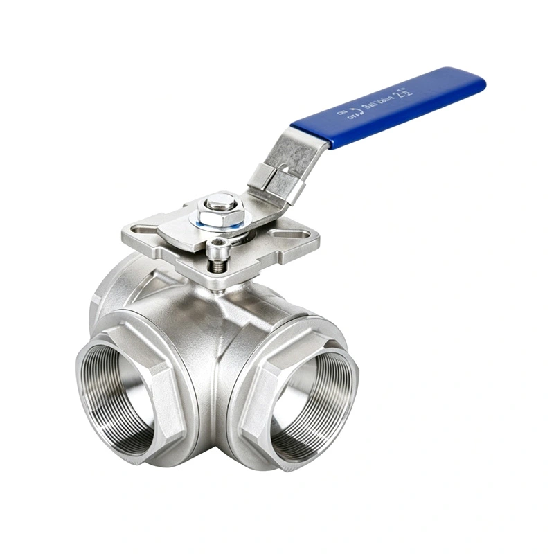
Table of Contents
- What Is a Three Way Ball Valve L Port?
- How Does an L-Port Three-Way Ball Valve Work?
- L-Port vs. T-Port: What Is the Difference?
- What Are the Main Advantages?
- Where Are L-Port Ball Valves Used?
- How to Choose the Right Valve
- Technical Specifications to Review
- Installation and Maintenance Recommendations
- Frequently Asked Questions
- Conclusion: Making the Right Flow Control Decision
What Is a Three Way Ball Valve L Port?
A three-way ball valve is a mechanical flow-control device with three ports and a rotating ball inside its body. The internal passage determines which ports communicate when the valve is operated. In an L-port configuration, the passage resembles the letter L, allowing the valve to direct fluid between selected connections.
For example, a pipeline may have one common connection and two alternative outlets. The valve can direct incoming fluid toward the first outlet or switch it to the second outlet, depending on the internal passage and handle position. The unused branch is isolated in the intended operating position when the valve's design supports that arrangement.
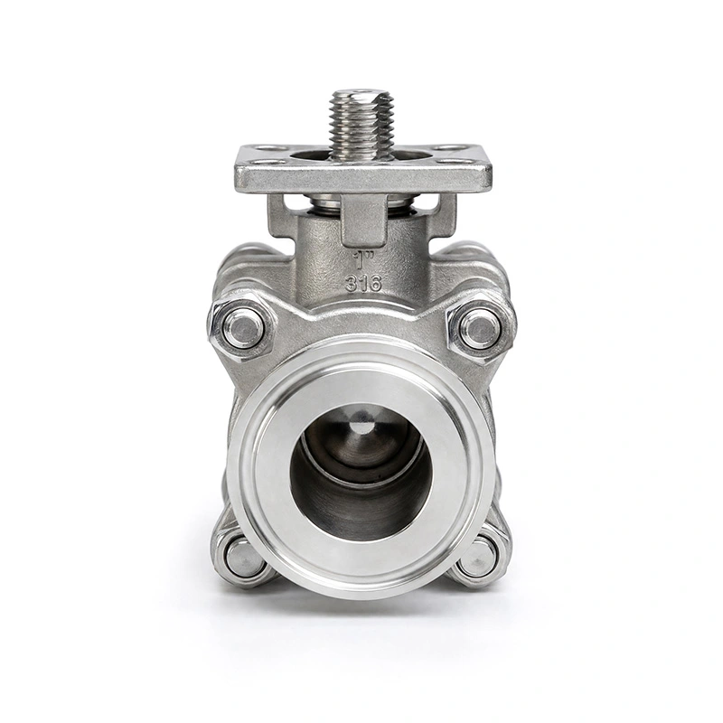
Shangtai's product combines this flow-routing principle with a three-piece body and extended butt-weld ends. The additional weld-end length provides working space for pipeline installation and can be useful in insulated or buried piping layouts where the specified design requires extra clearance.
Common construction considerations include:
- Valve body: Stainless steel or other specified materials selected according to the application.
- Ball and stem: Components responsible for directing flow and transmitting operating torque.
- Seats and seals: Parts that support sealing performance under the specified service conditions.
- Connections: Butt-weld, threaded, or other configurations depending on the selected model.
- Operating mechanism: A manual handle or a compatible actuator, where available.
The final configuration should always be checked against the manufacturer's approved drawings and technical documentation.
How Does an L-Port Three-Way Ball Valve Work?
The valve operates by rotating a specially drilled ball within the valve body. When the ball passage aligns with two selected ports, fluid can travel between those connections. Changing the ball's orientation changes the available flow path.
In a typical diverting arrangement, the operating sequence includes the following conditions:
- First flow position: The common port connects to one selected branch, allowing fluid to follow the first route.
- Changeover operation: The operator rotates the handle according to the manufacturer's operating instructions.
- Second flow position: The internal passage aligns with the alternative branch, redirecting the fluid.
- Isolation position, if designed: Certain L-port configurations provide a position that blocks all three ports. This capability must be verified for the specific valve.
Port numbering, handle orientation, rotation angle, and available stopping positions vary between designs. Therefore, operators should never assume that a particular handle direction always corresponds to the same flow path.
Before commissioning, review the valve's flow diagram and confirm the intended connections under every permitted operating position. This is especially important in automated systems, where an incorrect actuator sequence can interrupt production or send fluid to an unintended destination.
L-Port vs. T-Port: What Is the Difference?
Although both designs use three ports, their internal ball passages serve different purposes. Choosing between them depends primarily on whether the system needs to switch flow between branches or connect several paths for mixing and distribution.
| Comparison Factor | L-Port Three-Way Ball Valve | T-Port Three-Way Ball Valve |
|---|---|---|
| Internal passage | L-shaped passage | T-shaped passage |
| Primary function | Flow diversion and route selection | Flow mixing, distribution, or switching, depending on design |
| Typical flow path | Connects selected pairs of ports | Can connect different combinations of ports |
| Simultaneous connection of all three ports | Not provided by the standard L-shaped passage | Possible in suitable positions and configurations |
| Isolation capability | Some designs provide a fully closed position | Many configurations cannot isolate all ports in every operating position |
| Typical application | Selecting between outlets or alternative sources | Mixing streams or distributing flow |
The table describes general design principles rather than guaranteeing every valve's operating sequence. Manufacturers may offer different ball arrangements, seat configurations, and stop positions.
For applications where two fluid sources must remain separate, an L-port design may be appropriate if its approved flow diagram confirms the required isolation. Where simultaneous communication between several ports is necessary, a T-port design may be more suitable.
For additional background, review the manufacturer's L-port three-way ball valve product information before finalizing a selection.
What Are the Main Advantages?
1. Flexible Flow Routing
An L-port valve allows operators to switch between designated pipeline branches without installing separate valves at every changeover point. This can simplify the arrangement of equipment used for fluid transfer, source selection, and process routing.
2. Space-Efficient Pipeline Design
Combining multiple flow connections in one valve body can reduce the number of individual components required in suitable installations. Fewer components may also mean fewer connection points that require inspection, although the overall system design determines the actual savings.
3. Stainless Steel Material Options
Stainless steel construction can provide useful corrosion resistance in compatible industrial environments. The appropriate grade depends on the process medium, chloride concentration, cleaning chemicals, temperature, and other service conditions. Material selection should be based on verified compatibility rather than the assumption that all stainless steels perform identically.
4. Maintenance Access Through Three-Piece Construction
A three-piece body can make internal inspection and service more convenient because the valve can be disassembled according to the manufacturer's procedures. After the pipeline has been isolated, depressurized, drained, and made safe, qualified maintenance personnel can inspect serviceable components and replace compatible seats or seals when necessary.
5. Extended Butt-Weld Ends for Specific Installations
Extended butt-weld ends can provide additional clearance during pipeline welding, particularly in layouts involving insulation or buried piping. Correct installation remains essential: welding procedures must control heat input to avoid damaging seats, seals, or other temperature-sensitive internal components.
Where Are L-Port Ball Valves Used?
The ability to redirect flow makes this valve configuration useful in several industrial sectors. Its suitability depends on the process medium, pressure, temperature, connection arrangement, and required shut-off performance.
- Petrochemical processing: Switching compatible process streams between designated pipeline branches.
- Oil and gas systems: Selecting alternative flow routes in applications where the valve's pressure rating and material compatibility are appropriate.
- Thermal energy systems: Redirecting compatible fluids between process circuits or equipment connections.
- Water treatment: Switching water flows between selected treatment lines or system branches.
- Industrial equipment: Changing the fluid supply route to support different operating modes or maintenance arrangements.
For example, a water-treatment installation may use an L-port valve to select between two designated flow routes. During system design, engineers should verify the port map, the intended isolation state, and the consequences of changing the flow path before putting the valve into service.
Not every three-way ball valve is suitable for every fluid or operating condition. Abrasive particles, viscous media, corrosive chemicals, high differential pressure, and elevated temperatures can affect seat life and sealing performance. The valve must be selected for the actual service rather than the industry name alone.
How to Choose the Right Valve
Purchasing a three-way ball valve involves more than matching the nominal pipe diameter. A reliable selection process should begin with the required flow function and continue through material compatibility, mechanical ratings, installation dimensions, and maintenance requirements.
1. Define the Required Flow Pattern
Identify the common port, the alternative branches, and every required operating position. Obtain a manufacturer's flow diagram to verify which ports are connected and which are isolated in each position.
2. Confirm Pressure and Temperature Requirements
Check the rated operating pressure at the actual service temperature. Pressure ratings can change with temperature and material selection, so a maximum pressure value should never be considered independently of the specified conditions.
3. Select Compatible Body and Sealing Materials
Compare the process medium with the proposed body, ball, stem, seat, and seal materials. PTFE-based seats and reinforced PTFE variants have different mechanical and thermal characteristics. Chemical compatibility and the manufacturer's allowable service range should be confirmed for each application.
4. Check the Connection Standard
Verify the specified connection type, dimensions, and applicable standard. For butt-weld installations, review the end preparation and dimensional drawings. Threaded and welded connections are not interchangeable without an appropriately engineered piping arrangement.
5. Decide on Manual or Automated Operation
A manual handle may be sufficient for occasional route changes. Where frequent switching or remote control is required, ask whether a compatible pneumatic or electric actuator is available. Confirm operating torque, required travel, position feedback, and the desired response during power or air-supply failure.
6. Evaluate Inspection and Documentation Needs
For critical services, clarify material identification, pressure-test documentation, dimensional inspection, traceability, and any project-specific acceptance requirements. These records help purchasing teams and engineers verify that the supplied valve matches the approved specification.
Technical Specifications to Review
Shangtai's published product information provides a useful starting point for evaluating an L-port three-way ball valve with a three-piece body and extended butt-weld ends. The listed values below describe the referenced product configuration and should be confirmed against the quotation and current approved datasheet before purchase.
| Parameter | Published Product Information | Purchasing Consideration |
|---|---|---|
| Valve configuration | Three-way L-port ball valve | Confirm the flow diagram and operating positions. |
| Body construction | Three-piece body | Review maintenance access and service procedures. |
| Connection | Extended butt-weld ends | Confirm end dimensions and pipeline compatibility. |
| Size range | Published range: 1/4 inch to 6 inches | Confirm the required size and available configuration. |
| Pressure class | Class 150 | Verify the applicable pressure-temperature rating. |
| Maximum pressure | Published value: 285 PSI | Confirm the rating for the exact model and service temperature. |
| Design standard | ASME B16.34 | Confirm applicability to the supplied valve design. |
| Inspection standard | API 598 | Confirm the applicable test scope and acceptance criteria. |
| Published temperature range | -25°C to 150°C | Verify the allowable range for the selected materials and pressure. |
| Body material | ASTM A351 CF8M (316), as listed | Confirm the material specification and documentation. |
| Ball and stem materials | ASTM A182 F316, as listed | Confirm the bill of materials for the exact configuration. |
| Seat material | RPTFE, described as PTFE with 15% filler | Verify the actual seat compound and chemical compatibility. |
These figures are not universal ratings for all L-port valves. The product page also discusses alternative materials and sealing configurations. Buyers should request the latest technical drawing and written confirmation of the pressure-temperature envelope, connection details, and material composition for their order.
Installation and Maintenance Recommendations
Correct installation and planned maintenance help preserve valve performance and reduce avoidable downtime. The following practices are useful for engineering, commissioning, and maintenance teams.
- Inspect before installation: Check the valve body, weld ends, operating mechanism, and protective packaging for damage or contamination.
- Verify the flow direction: Compare the actual port arrangement with the approved piping diagram before connecting the valve.
- Use suitable welding procedures: For butt-weld designs, follow qualified procedures and control heat input in accordance with the manufacturer's instructions.
- Test the operating sequence: Where safe and appropriate, verify handle positions and flow-path indications before introducing the process medium.
- Prevent unsafe maintenance: Isolate the valve, relieve pressure, drain hazardous contents, and follow the site's lockout and safety procedures before disassembly.
- Inspect seats and seals: Check for wear, chemical damage, leakage, and operating difficulties at intervals appropriate to the service.
- Keep technical records: Document inspections, replacements, test results, and any changes to operating conditions.
Ball valves are generally intended for on-off service and flow routing, not continuous throttling unless the manufacturer specifically approves that duty. Operating a valve in an unsuitable partially open position may increase turbulence, erosion, or seat damage under certain conditions.
Frequently Asked Questions
1. What is the main function of a Three Way Ball Valve L Port?
Its primary function is to redirect fluid between selected pipeline branches. The L-shaped passage inside the ball connects designated ports according to the valve's orientation. The approved flow diagram should be consulted to confirm the exact operating sequence and isolation capability.
2. What is the difference between an L-port and a T-port ball valve?
An L-port design is mainly used for flow switching or diversion between selected ports. A T-port design offers additional connection patterns and may allow all three ports to communicate simultaneously. The correct option depends on the required process function and the manufacturer's port configuration.
3. Can an L-port three-way ball valve completely shut off flow?
Some L-port designs include an all-ports-closed position, while others have different operating arrangements. Complete isolation must be confirmed from the specific valve's flow diagram and sealing specifications. Where isolation is safety-critical, verify the required leakage performance and whether additional isolation equipment is necessary.
4. Which materials are suitable for an L-port ball valve?
Material selection depends on the fluid, corrosion exposure, pressure, temperature, and cleaning requirements. Stainless steel grades such as 304 or 316 may suit many applications, while PTFE-based or reinforced seats may be appropriate for certain services. The complete wetted-material combination must be checked for compatibility.
5. What information is needed to request a quotation?
Provide the nominal valve size, required port arrangement, connection type, pressure and temperature conditions, process medium, preferred materials, quantity, and operating method. Pipeline drawings, the required flow sequence, and project-specific inspection requirements can help the supplier confirm a suitable configuration.
6. Why consider a three-piece valve with extended butt-weld ends?
A three-piece construction can simplify access to serviceable internal components, subject to the manufacturer's maintenance procedure. Extended butt-weld ends can provide additional clearance for welding and may suit certain insulated or buried piping arrangements. The dimensions and installation method should be checked before ordering.
Conclusion: Making the Right Flow Control Decision
A three-way ball valve with an L-port passage can provide a practical solution for switching fluid between designated pipeline branches. Its effectiveness depends on selecting the correct port arrangement, verifying pressure and temperature limits, choosing compatible materials, and ensuring that the valve's operating positions match the process requirements. Construction details such as a three-piece body and extended butt-weld ends can also influence installation planning and long-term maintenance.
Shangtai offers product information and configuration options to support industrial valve selection. If you are comparing L-port designs, planning a new piping system, or replacing an existing valve, review the Three Way Ball Valve L Port specifications and prepare your operating requirements before placing an order. Contact our team to discuss your application, confirm technical details, and request a suitable quotation. Please contact us today to explore valve solutions tailored to your industrial flow-control needs.
Related News
- Technical Insight: 2000 WOG 2-Piece High Platform Ball Valve - Design Features & Application Environments
- Why Are Stainless Steel Valves Preferred in Data Center Liquid Cooling Pipelines?
- Why Is a 1PC Electropolished Stainless Steel Direct Mount Ball Valve a Smart Choice for Modern Fluid Control
- Stainless Steel Ball Valve Seal Selection: A Decision-Making Guide Based on Temperature and Pressure for Inquiries
- Check Valve Market Advances with Major Projects and Technological Breakthroughs
- Flanged Ball Valves: Market Growth and Application Expansion
Leave me a message
New Products
News Recommendations