Globe Valves
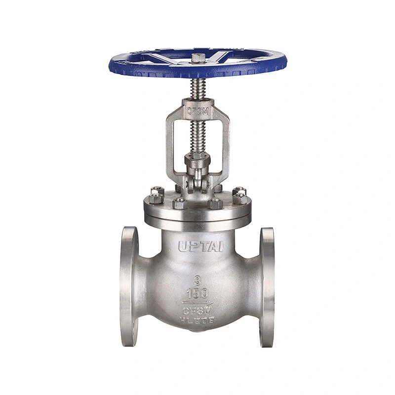
ANSI Standard Flanged Globe Valve
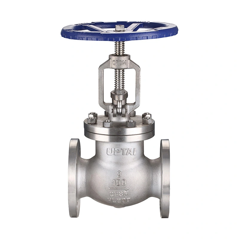
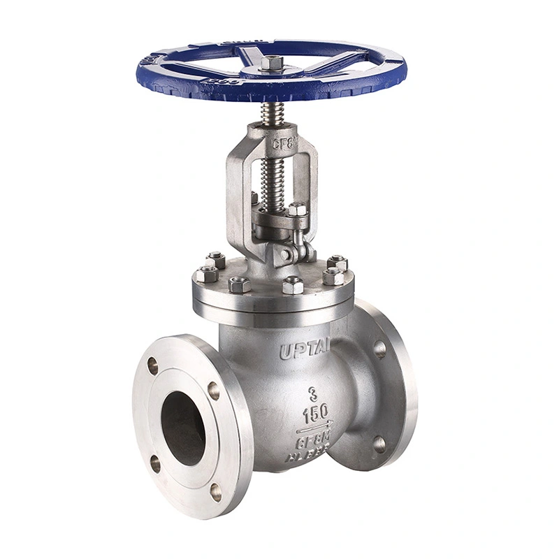
Shangtai ANSI standard flanged globe valves deliver precise flow regulation and reliable tight shutoff for industrial pipelines. Manufactured in strict compliance with ANSI B16.34 specifications, they feature robust structure and stable sealing performance. As a direct factory with rigorous quality control and export-grade packaging, we supply durable globe valves for petrochemical, power and water treatment applications.
The ANSI Standard Flanged Globe Valve is a Class 150 stainless steel globe valve for industrial piping where flow regulation and shut-off are required. Its disc moves toward and away from the seat to change the flow area, making the valve suitable for applications that require more controlled flow adjustment than a simple isolation valve.
Shangtai supplies this valve with RF-compatible flanged ends and handwheel operation. The available configuration includes CF8/CF8M body and disc materials, F304/F316 stems, and the listed seat options. The valve is available in sizes from 2" to 18" for industrial piping and process equipment.
Main Dimensions
| Size | 2" - 18" |
| Pressure Class | CL150 |
| Design and manufacturing standards | ASME B16.34 / API 603 |
| Face-to-Face Dimensions Standard | ASME B16.10 |
| End Connections | RF-compatible flanges |
| Testing and inspection | API598 |
| Connection Standards | ASME B16.5 |
| Pressure-Temperature Ratings | ASME B16.34 |
| NACE Standards | NACE MR0175 / ISO 15156 |
| Valve Operator | Handwheel |
| Maximum Working Pressure | 285 PSI |
| Temperature Range | -29°C ~ +120°C |
| Body Material | ASTM A351 CF8 / CF8M |
| Disc Material | ASTM A351 CF8 / CF8M |
| Stem Material | ASTM A182 F304 / F316 |
| Seat Material | ASTM A182 F304 / ASTM A351 CF8M+Stellite 6 |
| Options | Other materials are available upon request. |
Valve Design
Disc and Seat
The disc travels along the valve axis and closes against the seat to stop flow. Raising the disc increases the flow passage, while lowering it reduces or closes the passage. This linear movement allows the valve to be used for both throttling and shut-off service.
Stainless Steel Materials
The body and disc are available in ASTM A351 CF8 or CF8M. Stem options include ASTM A182 F304 and F316. The specified seat materials are ASTM A182 F304 and ASTM A351 CF8M with Stellite 6. The selected material combination should match the process medium and operating temperature.
Handwheel Operation
The handwheel provides manual control of the disc position. The valve can be opened, closed or adjusted to an intermediate position according to the process requirement. If the handwheel becomes difficult to operate, the valve should not be forced.
Flanged Connection
The valve uses RF-compatible flanged ends for connection to matching pipeline flanges. The specified connection standard is ASME B16.5, while the face-to-face dimension follows the listed ASME B16.10 requirement.
Flanged installation allows the valve to be removed from the pipeline without cutting the pipe. Before installation, check the flange size, pressure class, gasket, bolting and face-to-face dimension. The pipeline should be properly aligned to avoid placing excessive mechanical load on the valve.
Pressure and Temperature
The valve is specified as CL150 with a maximum working pressure of 285 PSI. The pressure-temperature rating varies with material and operating temperature, so the actual service conditions need to be considered when selecting the valve.
The listed temperature range is -29°C to +120°C. The seat and other sealing components are particularly important when the valve is used near the temperature limits.
For steam, hot water, oil, gas and chemical service, the medium temperature, pressure and material compatibility should be checked against the selected valve configuration.
NACE Service
The specification includes NACE MR0175 / ISO 15156. Where the valve is intended for sour-service applications, the material grades and applicable NACE requirements need to match the actual service conditions.
For such applications, the project specification may also define requirements for material condition, hardness, inspection and supporting documentation.
Applications
Steam and Utility Lines: Used for flow adjustment and shut-off in compatible steam, condensate and utility piping.
Oil and Gas: Used in process and utility lines where manual flow control or isolation is required.
Petrochemical Systems: Suitable for compatible oil, gas and process fluids where throttling or shut-off is required.
Water Treatment: Used in process and utility piping for controlling compatible water and liquid media.
Power Generation: Applicable to selected auxiliary and utility piping within the specified pressure and temperature range.
General Industrial Piping: Used on process equipment, pump systems and other pipelines requiring manual flow adjustment.
Selection and Installation
Valve selection starts with the pipe size, pressure class, medium, operating pressure and temperature. The body, disc, stem and seat materials are then selected according to the service conditions.
For replacement applications, the existing valve size, flange dimensions, face-to-face length and operating arrangement should be compared with the new valve before ordering.
During installation, keep the flange faces clean and use the specified gasket and bolting. After the valve is installed, check the handwheel operation and confirm that the disc can travel through its full range without abnormal resistance.
Testing and Inspection
Material Inspection
Body and trim materials are checked against the specified grades and order information. Material records can be supplied when required.
Dimensional Inspection
Face-to-face dimensions, flange dimensions and other key machining dimensions are checked against the applicable product specification.
Pressure and Seat Testing
Shell and seat tests are carried out according to the specified inspection requirements. Test results and acceptance criteria can be documented according to the order requirements.
Final Inspection
Before shipment, the valve is checked for body condition, flange surfaces, handwheel operation, identification markings and overall assembly.
Packaging
Flange faces and other connection surfaces are protected before packing. The valve is packed according to its size and shipping method to reduce the risk of impact and contamination during transportation.
Export packaging can include cartons, protective materials and plywood cases according to the valve dimensions and transportation requirements. Product markings and shipping documents can be prepared according to the order.
FAQ
Q1: What is an ANSI Standard Flanged Globe Valve used for?
An ANSI Standard Flanged Globe Valve is used for regulating and shutting off compatible fluids in industrial piping. The disc-and-seat design allows the flow passage to be adjusted during operation, making it suitable for applications where flow control is required.
Q2: What is the difference between a globe valve and a gate valve?
A globe valve uses a disc that moves toward the seat and is commonly used for throttling and flow adjustment. A gate valve moves the gate away from the flow path and is generally used for isolation rather than continuous throttling.
Q3: Why are flanged ends used on this valve?
Flanged ends provide a bolted connection to the pipeline and allow the valve to be removed for maintenance without cutting the pipe. They are commonly used on industrial piping systems where standardized flange dimensions are required.
Q4: What materials are available?
The listed configuration includes CF8/CF8M for the body and disc, F304/F316 for the stem, and the specified seat material options. Other materials can be considered according to the operating medium and temperature.
Q5: Can the valve be used for steam?
Yes, provided the pressure, temperature and material configuration are within the specified operating limits. The seat and sealing materials should be checked for the actual steam conditions.
Q6: What information is needed to select the correct valve?
Important information includes pipe size, pressure class, flange standard, medium, operating pressure, temperature, material requirements and any NACE or project-specific requirements.
Q7: How should the valve be maintained?
Check the handwheel, stem, packing area, flange connection and sealing condition during routine maintenance. If leakage or abnormal operating resistance occurs, isolate and depressurize the pipeline before inspection.
Send Inquiry
Contact Info
-
Address
JINHAI 3RD ROAD, YONGXING SUB-DISTRICT, LONGWAN DISTRICT, WENZHOU CITY, ZHEJIANG PROVINCE, CHINA
-
Tel
-
Email
Contact our team with product specifications, working conditions, connection standards, pressure requirements, or drawings. We provide valve recommendations, customization options, pricing, and technical support according to your project needs.
News Recommendations