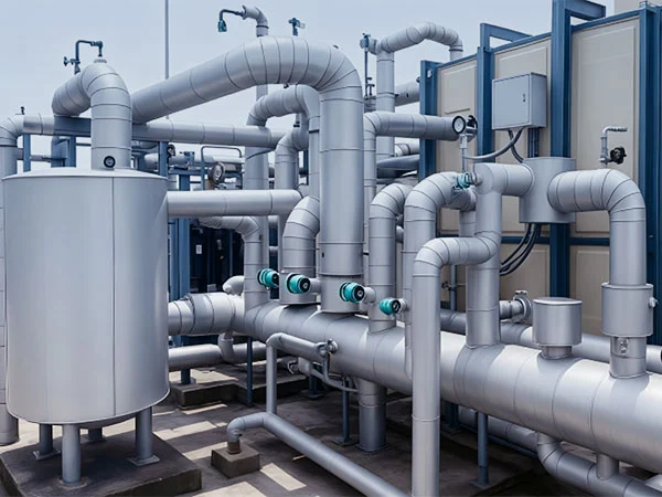
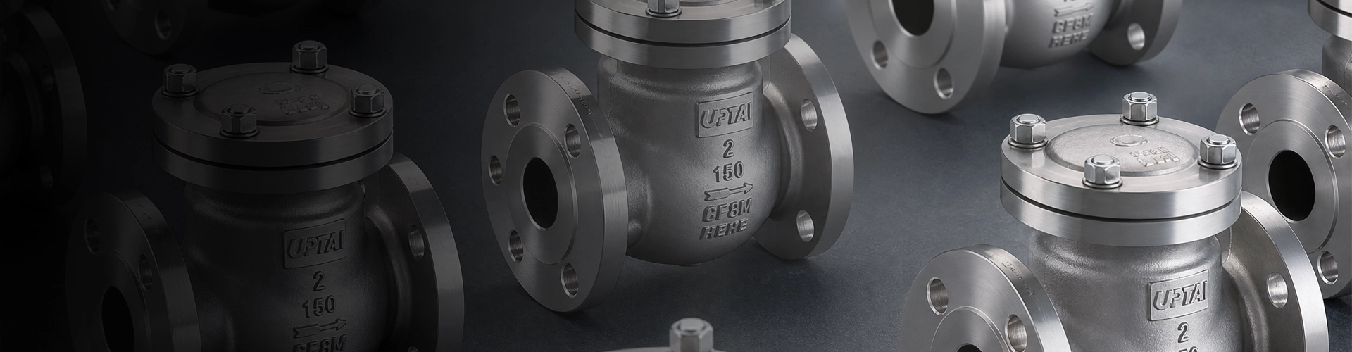
Check Valves
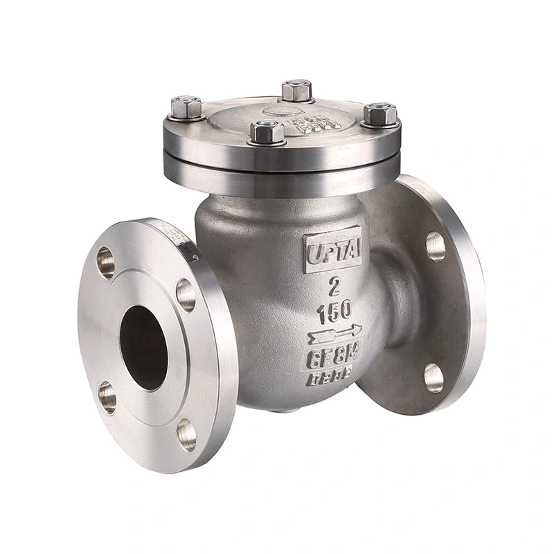
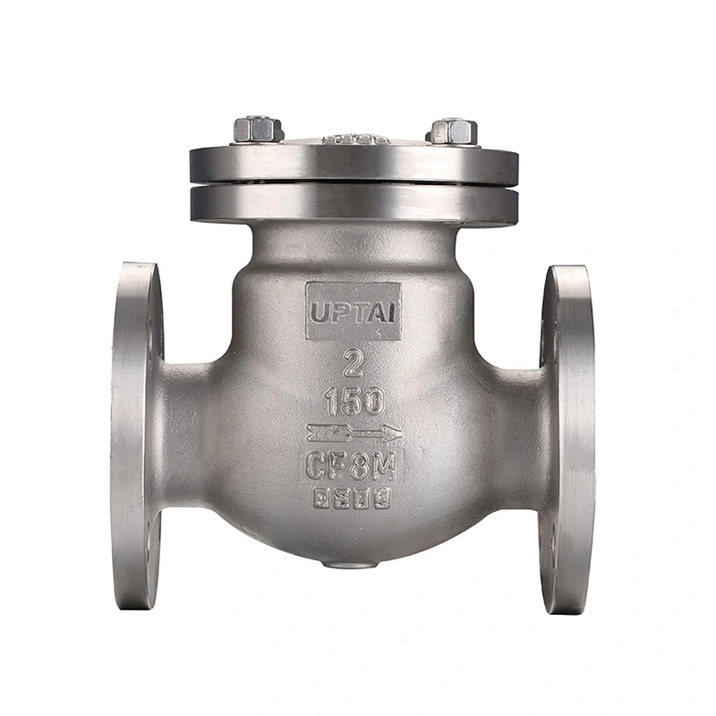
Swing Check Valve ANSI Class 150
Shangtai Swing Check Valve ANSI Class 150 uses a hinged disc to control reverse flow in pipelines. The disc opens when the medium flows forward and closes when the flow changes direction, preventing backflow to pumps, compressors and other equipment. It is available for large-diameter piping in water treatment, petrochemical, power and general industrial systems, with different materials and connection options available according to the service conditions.
The Swing Check Valve ANSI Class 150 is a non-return valve with a hinged disc for controlling flow direction in industrial piping. The disc moves with the process flow and closes when the flow falls or reverses. No external actuator is required for normal operation.
This valve is available for compatible water, steam, oil, gas, seawater and industrial fluids. The specified configuration uses CF8M stainless steel for the body and disc and F316 for the seat. Valve selection should be based on the actual medium, pressure, temperature, pipe size and installation arrangement.
Main Dimensions
| Size | 1/4" - 6" |
| Pressure Class | CL150 |
| Thread Standard | NPT、BSP |
| Max Pressure | 285PSI |
| Design and manufacturing standards | ASME B16.34 |
| Testing and inspection | API598 |
| Pressure-Temperature Ratings | ASME B16.34 |
| Temperature Range | -25℃~150℃ |
| Body material | ASTM A351 CF8M(316) |
| Disc Material | ASTM A351 CF8M(316) |
| Seat Material | ASTM A182 F316 |
| Options | Other materials are available upon request. |
Valve Construction
The valve consists mainly of a body, hinged disc, seat, hinge mechanism and sealing components. The disc is mounted inside the body and rotates around its hinge during operation. This arrangement allows the valve to open with forward flow and return toward the seat when the flow condition changes.
Hinged Disc
The disc moves away from the seat as the medium flows through the valve. When the forward flow decreases, the disc moves back toward the closed position. The disc movement is affected by flow velocity, installation position and the internal valve geometry.
Seat and Sealing Surface
The listed seat material is ASTM A182 F316. The seat and disc sealing surfaces form the shut-off interface when the valve closes. Their condition should be checked during maintenance if leakage or abnormal closing is observed.
Flow Direction and Installation
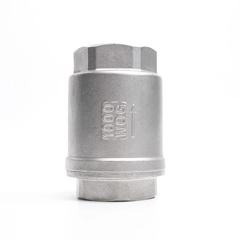
The valve should be installed according to the flow direction marked on the body. Before installation, check the arrow, connection dimensions and available clearance around the valve. The disc must have enough space to move through its operating range without contacting surrounding piping or equipment.
Horizontal Installation
Horizontal installation is commonly used for swing check valves. The valve should be positioned so that the disc can move freely and return to the seat when forward flow decreases.
Vertical Installation
Vertical installation depends on the valve design and flow direction. The installation should allow the disc to close correctly under the actual flow conditions. The specific model and pipeline arrangement should be confirmed before installation.
Pipeline Connection
The listed connection specification includes NPT and BSP threads. The mating pipe or fitting should use the corresponding thread specification. During installation, avoid excessive tightening force that could damage the valve body or threaded connection.
Flow and Pressure Characteristics
When the valve is open, the disc moves away from the flow passage. The pressure drop through the valve depends on its size, internal passage, flow rate and medium properties. For high-flow systems, valve size should be selected according to the required flow rate rather than pipe size alone.
The listed pressure class is CL150, with a maximum pressure of 285 PSI. The allowable working pressure can vary with temperature and material, so the operating pressure and temperature should be checked together with the applicable pressure-temperature rating.
For pump discharge lines and other systems with changing flow conditions, the valve response should be considered as part of the overall pipeline design. Rapid changes in flow can affect disc movement and system pressure.
Water Hammer Considerations
Water hammer may occur when flowing fluid is stopped or changes direction rapidly. A check valve can contribute to pressure surge if the disc closes while significant flow is still moving through the pipeline.
The severity of the pressure surge depends on factors such as flow velocity, pipe length, fluid properties, valve closing characteristics and pump operation. Where water hammer is a concern, the check valve and the complete piping system should be evaluated together.
Slow-closing, damping or counterweight configurations may be considered for systems that require more controlled disc movement. The appropriate structure depends on the actual pipeline conditions and project requirements.
Materials and Service Conditions
The specified body and disc materials are ASTM A351 CF8M (316), while the seat is ASTM A182 F316. These materials are suitable for many industrial applications where stainless steel is compatible with the process medium.
Material compatibility should be checked against the actual fluid composition, concentration, temperature and pressure. Seawater and chemical service may require additional consideration of chloride exposure and corrosion conditions.
Other material options are available upon request. For special applications, the required body, disc and seat materials should be confirmed before production.
Typical Applications
Pump Discharge Piping: Used downstream of pumps to limit reverse flow when the pump stops or operating conditions change.
Water Treatment: Applied in compatible water and process lines where automatic one-way flow control is required.
Petrochemical Piping: Used with compatible oil, gas and process fluids within the specified pressure, temperature and material limits.
Power and Utility Systems: Suitable for selected water, utility and process lines where reverse flow needs to be controlled.
Seawater Systems: Stainless steel configurations can be considered where the material is suitable for the actual seawater conditions.
General Industrial Piping: Used on equipment and process lines where a self-operated non-return function is required.
Selection Guide
| Parameter | Selection Options / Requirements |
| Nominal Size | DN or NPS dimension |
| Pressure Rating | PN or Class |
| Connection Type | Flanged, welded, wafer, etc. |
| Installation Orientation | Horizontal or vertical installation |
| Medium | Water, steam, oil, gas, seawater or other fluids |
| Working Pressure | Normal operating pressure and maximum pressure |
| Working Temperature | Ambient, medium, high or cryogenic temperature |
| Body Material | Carbon steel, stainless steel, alloy steel, duplex stainless steel, etc. |
| Sealing Type | Soft seat, metal-to-metal hard seat, overlay welded seat |
| Water Hammer Resistance | Standard, slow-closing, damping or counterweight type |
| Connection Standard | GB, ANSI, EN, DIN, etc. |
| Special Requirements | Anti-corrosion, wear-resistant, cryogenic service, oil-free & degreased, seawater service, etc. |
For quotation and technical review, provide the nominal size, pressure rating, connection type, installation orientation, medium, operating pressure, temperature and material requirements. Special service conditions such as seawater, corrosive media or water hammer should also be identified.
Testing and Inspection
The specified design and manufacturing standard is ASME B16.34, and API 598 is listed for testing and inspection. The applicable inspection procedure can cover the valve body, sealing areas, dimensions and pressure performance.
Shell Test
The shell test checks the pressure boundary of the assembled valve under the specified test conditions. The test pressure and holding time should follow the applicable inspection requirements.
Seat Leakage Test
The seat test checks whether the closed valve meets the specified leakage acceptance criteria. The test conditions depend on the applicable standard and valve specification.
Final Inspection
Final inspection can include dimensional checks, connection inspection, surface condition, identification markings and operating movement. Required inspection records or material documentation can be supplied according to the order requirements.
Operation and Maintenance
Before commissioning, check the valve orientation, flow direction and pipeline cleanliness. Foreign particles left in the pipeline can affect the disc or sealing surface during operation.
During service, unusual noise, vibration, repeated disc movement or reverse flow should be investigated. These conditions may be related to flow velocity, installation, valve sizing or changes in the operating system.
Before inspection or maintenance, isolate and depressurize the pipeline. Check the disc, hinge mechanism, seat surface and body connection for wear, deposits or damage. Replace components when their condition no longer meets the applicable maintenance requirements.
FAQ
Q1: What is a Swing Check Valve ANSI Class 150?
A Swing Check Valve ANSI Class 150 is a hinged-disc check valve with a Class 150 pressure rating. It uses the process flow to open the disc and closes when the flow decreases or reverses, making it suitable for automatic reverse-flow prevention in compatible industrial piping.
Q2: Does a swing check valve require an actuator?
No. The disc operates automatically according to the flow and pressure conditions in the pipeline. No pneumatic, electric or hydraulic actuator is required for normal check-valve operation.
Q3: What information is needed when selecting a swing check valve?
Key information includes pipe size, pressure class, connection type, installation direction, medium, operating pressure, temperature, material requirements and any special requirements related to corrosion, water hammer or inspection.
Q4: Can stainless steel construction be used for seawater?
It can be considered for suitable seawater applications, but material compatibility should be evaluated based on chloride concentration, temperature, flow conditions and other corrosion factors. The stainless steel grade should be confirmed before selection.
Q5: What can cause reverse flow after the valve is installed?
Possible causes include incorrect installation direction, a disc that cannot move freely, damaged sealing surfaces, foreign material inside the valve, unsuitable sizing or operating conditions outside the intended range. The valve and surrounding piping should be inspected after the system has been safely isolated.
Q6: Can the valve be used for high-temperature media?
The listed temperature range is -25℃ to 150℃. Actual use at elevated temperature should be checked against the pressure-temperature rating and the compatibility of the body, disc and seat materials with the medium.
Q7: Are other materials available?
Yes. Other material configurations are available upon request. The required material should be specified according to the medium, pressure, temperature, corrosion conditions and applicable project requirements.
Send Inquiry
Contact Info
-
Address
JINHAI 3RD ROAD, YONGXING SUB-DISTRICT, LONGWAN DISTRICT, WENZHOU CITY, ZHEJIANG PROVINCE, CHINA
-
Tel
-
Email
Contact our team with product specifications, working conditions, connection standards, pressure requirements, or drawings. We provide valve recommendations, customization options, pricing, and technical support according to your project needs.
Related Products
News Recommendations