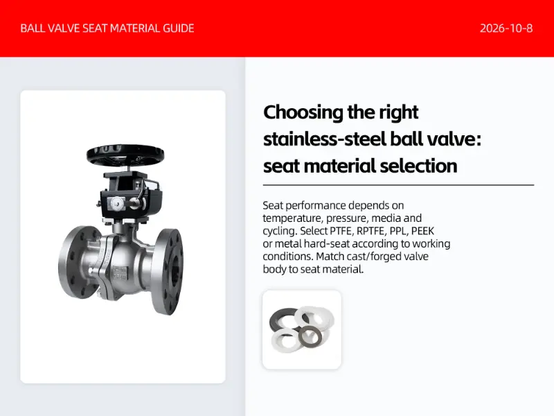
Flange Ball Valves
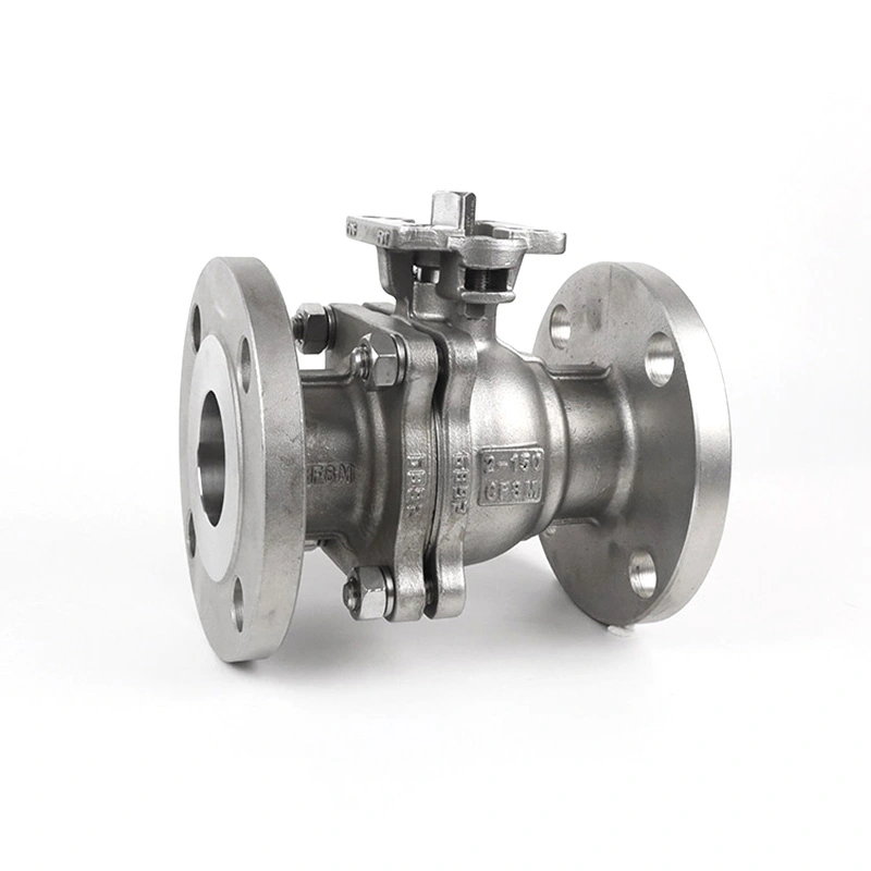
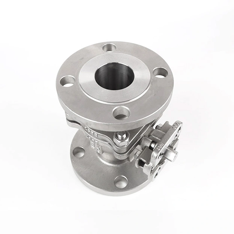
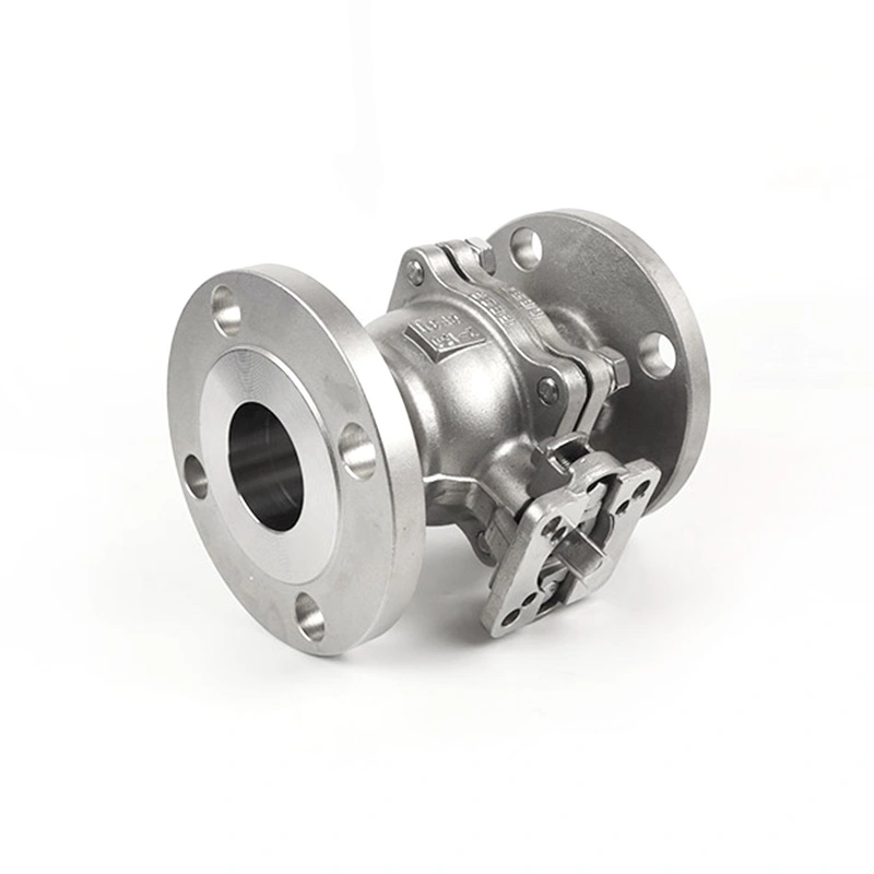
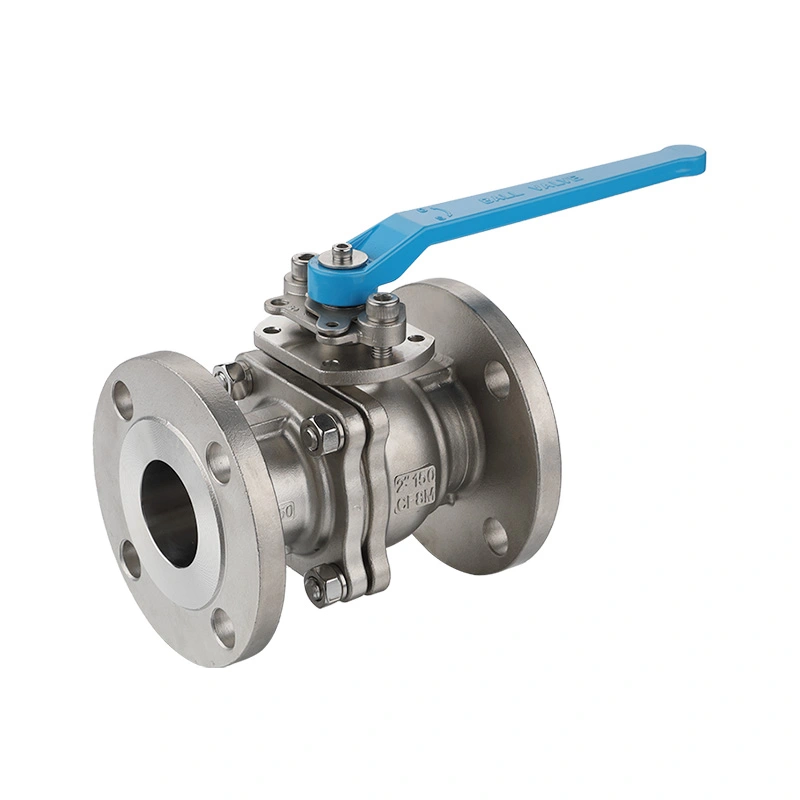
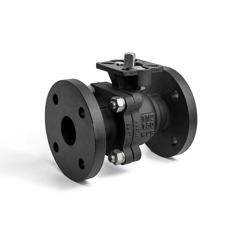
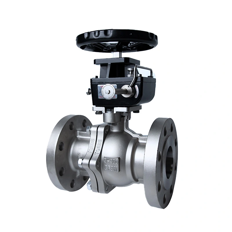
ANSI Class 150 Flanged Ball Valve with ISO 5211 Base for Actuator
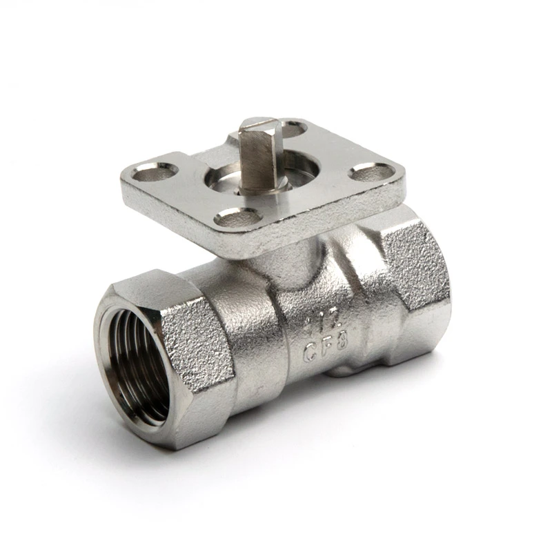
ANSI Class 150 Flanged Ball Valve with ISO 5211 Base for Actuator is designed for industrial pipeline isolation and automated fluid control. The flanged connection suits Class 150 piping systems, while the ISO 5211 mounting base allows pneumatic or electric actuators to be installed directly. Shangtai manufactures the valve in Wenzhou, China, with ISO 9001 and CE documentation available for applicable configurations.
For automated pipeline isolation, the valve configuration needs to match the piping standard, pressure class, connection dimensions and actuator interface. The ANSI Class 150 Flanged Ball Valve with ISO 5211 Base for Actuator combines a Class 150 flanged connection with an ISO 5211 mounting interface, allowing the valve to be configured for manual operation or part-turn pneumatic and electric actuation. The actual valve and actuator combination should be selected according to the required torque, operating conditions and pipeline configuration.
Shangtai manufactures industrial ball valves in Wenzhou, Zhejiang, China. Production covers machining, assembly and pressure testing, with material and dimensional requirements checked according to the applicable product specification. Drawings, material requirements and actuator information can be reviewed when a specific valve configuration is required.
Main Dimensions
| Size | 1/2inch - 8inch |
| Pressure Class | CL150 |
| End Connections | Flange |
| Max Pressure | 285PSI |
| Design and manufacturing standards | ASME B16.34 |
| Testing and inspection | API598 |
| Flange dimensions and bolt hole details | ASME B16.50 |
| Pressure-Temperature Ratings | ASME B16.34 |
| Connection Ends | RF Flanged |
| Temperature Range | -25℃~150℃ |
| Body material | ASTM A351 CF8M(316) |
| Ball Material | ASTM A182 F316 |
| Stem Material | ASTM A182 F316 |
| Seat Material | RPTFE(PTFE+15%fv) |
| Options | Other materials are available upon request. |
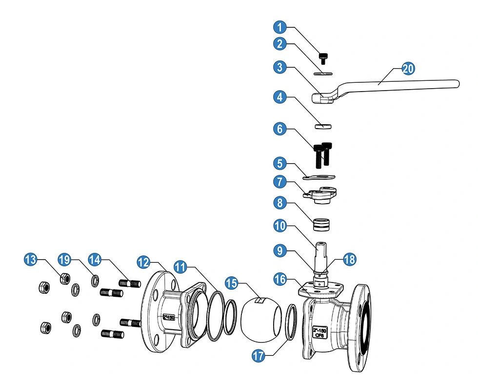
Valve Construction and Actuator Interface
The valve uses a flanged body for connection to compatible RF pipeline flanges. The 316 stainless steel body, F316 ball and F316 stem listed in the main specification provide the primary material configuration, while the RPTFE seat is intended for applications where the seat material is compatible with the operating medium and temperature.
The ISO 5211 mounting base provides a standardized interface for attaching compatible part-turn actuators or an intermediate mounting arrangement. ISO 5211 specifies actuator attachment flange and driving-component dimensions, so the actuator interface should be matched with the valve mounting size and required operating torque rather than selected by valve size alone.
For automated service, the valve torque, actuator output, mounting interface, rotation direction and available power or air supply should all be confirmed before assembly. Limit switches, solenoid valves, positioners and other control accessories can be selected according to the automation system.
Materials and Component Configuration
| No | Name | Material |
| 1 | Bolt | SS 304 |
| 2 | Washer | SS 304 |
| 3 | Handle | Cast Aluminium |
| 4 | retaining ring | SS |
| 5 | orientation patch | SS 304 |
| 6 | Bolt | SS 304 |
| 7 | Gland | SS 304 |
| 8 | Stem packing | PTFE |
| 9 | Friction ring | PTFE |
| 10 | Stem | SS 304 |
| 11 | Gasket | PTFE |
| 12 | Cap | SS 304 (CF8) |
| 13 | Nut | SS 304 |
| 14 | Stud Bolt | SS 304 |
| 15 | Ball | SS 304 |
| 16 | Body | SS 304(CF8) |
| 17 | Ball seat | RPTFE |
| 18 | Antistatic device . | SS 304 |
| 19 | Spring Washer | SS 304 |
| 20 | Handle Sleeve | PVC |
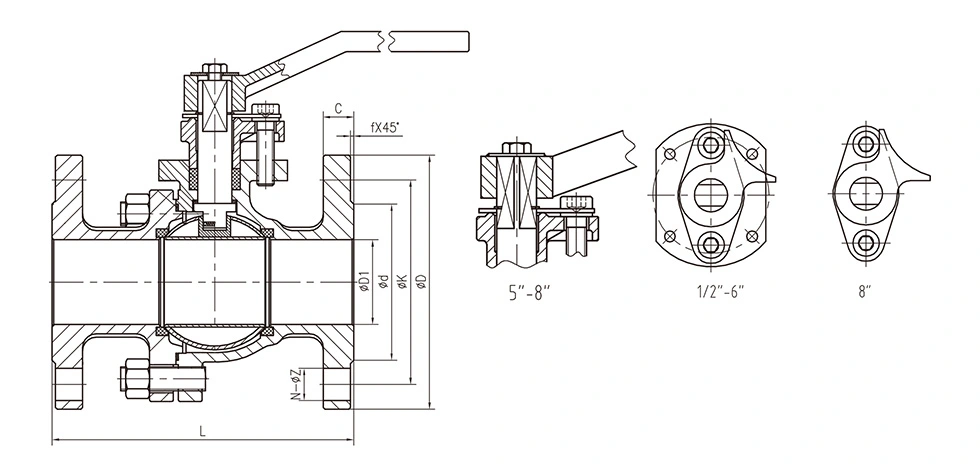
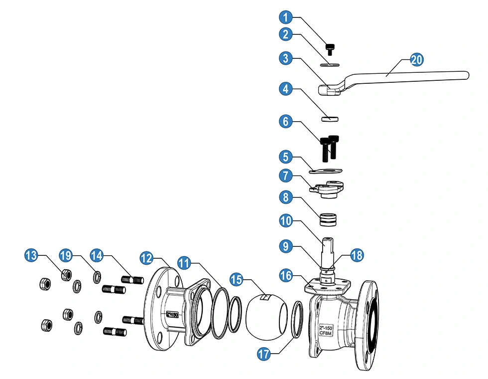
The component list above represents one material configuration. The product specification also provides a 316 stainless steel configuration, allowing the wetted components to be selected according to the required corrosion resistance and service conditions. Material selection should be confirmed against the actual purchase specification and fluid compatibility requirements.
General Dimensions:
| NO | Size | Dimensions (mm) | |||||||
| D1 | d | K | D | C | f | N-ΦZ | |||
| S063-04 | 1/2" | 15 | 34.9 | 60.3 | 90 | 10 | 2 | 4-16 | |
| S063-05 | 3/4" | 20 | 42.9 | 69.9 | 100 | 10.9 | 2 | 4-16 | |
| S063-06 | 1" | 25 | 50.8 | 79.4 | 110 | 11.6 | 2 | 4-16 | |
| S063-07 | 1 1/4" | 32 | 63.5 | 88.9 | 115 | 13.2 | 2 | 4-16 | |
| S063-08 | 1 1/2" | 38 | 73 | 98.4 | 125 | 14.7 | 2 | 4-16 | |
| S063-09 | 2" | 50 | 92.1 | 120.7 | 150 | 16.3 | 2 | 4-19 | |
| S063-10 | 2 1/2" | 65 | 104.8 | 139.7 | 180 | 17.9 | 2 | 4-19 | |
| S063-11 | 3" | 80 | 127 | 152.4 | 190 | 19.5 | 2 | 4-19 | |
| S063-12 | 4" | 100 | 157.2 | 190.5 | 230 | 24.3 | 2 | 8-19 | |
| S063-13 | 5" | 125 | 185.7 | 215.9 | 255 | 24.3 | 2 | 8-22 | |
| S063-14 | 6" | 150 | 215.9 | 241.3 | 280 | 25.9 | 2 | 8-22 | |
| S063-15 | 8" | 200 | 269.9 | 298.5 | 345 | 29 | 2 | 8-22 | |
| No | Name | Material |
| 1 | Bolt | SS 304 |
| 2 | Washer | SS 304 |
| 3 | Handle | Cast Aluminium |
| 4 | retaining ring | SS |
| 5 | orientation patch | SS 304 |
| 6 | Bolt | SS 304 |
| 7 | Gland | SS 304 |
| 8 | Stem packing | PTFE |
| 9 | Friction ring | PTFE |
| 10 | Stem | SS 304 |
| 11 | Gasket | PTFE |
| 12 | Cap | SS 316 (CF8M) |
| 13 | Nut | SS 304 |
| 14 | Stud Bolt | SS 304 |
| 15 | Ball | SS 316 |
| 16 | Body | SS 316(CF8M) |
| 17 | Ball seat | RPTFE |
| 18 | Antistatic device . | SS 316 |
| 19 | Spring Washer | SS 304 |
| 20 | Handle Sleeve | PVC |
Key Features
Class 150 Flanged Pipeline Connection
The RF flanged end configuration provides a bolted connection between the valve and the pipeline. Flange size, bolt-hole arrangement, facing type and related dimensions should be matched with the mating pipeline flange before installation. ASME B16.5 covers pipe flanges and flanged fittings in NPS 1/2 through NPS 24 and includes Class 150 flange dimensions and pressure-temperature requirements.
ISO 5211 Actuator Mounting
The actuator mounting interface is intended for part-turn automation. ISO 5211 defines the attachment interface dimensions and driving-component dimensions used to connect compatible actuators to industrial valves. The mounting size and actuator output should therefore be checked together with the valve operating torque.
Stainless Steel Pressure-Boundary Components
The main specification uses ASTM A351 CF8M (316) for the body, ASTM A182 F316 for the ball and stem, and RPTFE for the seat. This material combination can be considered for water, oil, gas and other compatible media where the selected materials meet the required chemical and temperature conditions.
Quarter-Turn On/Off Operation
The ball valve uses a quarter-turn mechanism to move between the open and closed positions. It is primarily intended for isolation service rather than continuous throttling. If flow regulation is required, the suitability of the valve, seat and operating conditions should be evaluated before selection.
Antistatic Construction
The material lists include an antistatic device for the valve configuration. Where antistatic performance is required by the application, the complete valve specification and applicable testing requirements should be confirmed with the order documentation.
Typical Applications
Water Treatment: Suitable for isolation of compatible water lines, process equipment and treatment skids where a flanged connection is required.
Oil and Gas Systems: Applicable to compatible oil and gas pipelines and equipment when the valve materials, pressure class and sealing configuration meet the service requirements.
Chemical Processing: Can be used for process-fluid isolation when the body, ball, stem, seat and gasket materials are chemically compatible with the medium.
Industrial Process Equipment: The actuator mounting interface allows the valve to be incorporated into automated skids, manifolds and equipment requiring remote open/close control.
General Pipeline Isolation: Suitable for industrial piping systems that require a Class 150 flanged ball valve and manual or automated shut-off operation.
Actuator Selection
Actuator selection should be based on the valve's required operating torque rather than the nominal pipe size alone. The valve size, seat material, differential pressure, medium, temperature and operating frequency can all affect the torque requirement.
For pneumatic actuation, confirm the available air pressure, actuator output torque, fail position and control accessories. For electric actuation, check the required torque, power supply, operating cycle and feedback requirements. The ISO 5211 mounting interface should also correspond to the selected actuator and coupling arrangement.
Selection and Installation Considerations
Before ordering, confirm the nominal size, Class 150 pressure class, flange dimensions, RF facing, operating pressure, temperature, medium and required body and trim materials. For automated valves, provide the actuator type, required torque, mounting interface and control requirements.
Before installation, inspect the flange faces and valve ends for damage or contamination. Align the mating flanges correctly and tighten the bolts evenly using a suitable gasket and the applicable installation procedure. Avoid forcing the pipeline into alignment through the valve body.
After actuator installation, verify the rotation direction and open/close limits before placing the valve into service. Heavy actuators or gearboxes should be adequately supported where required so that excessive external loads are not transferred to the valve mounting interface.
Usage Precautions
Operate the valve within the specified pressure and temperature limits. The 285PSI value in the product table should not be treated as a universal allowable pressure for every size and temperature; the applicable pressure-temperature rating should be confirmed for the actual configuration.
Flush the pipeline before commissioning to reduce the possibility of debris entering the valve and damaging the seat or sealing surfaces.
Do not use the ball valve for continuous throttling unless the application has been technically evaluated for the selected seat and operating conditions.
Before maintenance, isolate and depressurize the pipeline and confirm that the valve is safe to service. For automated valves, disconnect or isolate the actuator power or control source as required by the applicable maintenance procedure.
Quality Inspection and Documentation
Production inspection can cover material verification, dimensional inspection, body assembly and pressure testing according to the applicable product and order requirements. API 598 is used for valve inspection and testing requirements, while ASME B16.34 addresses relevant valve design, pressure-temperature and dimensional requirements.
For projects requiring traceability, the material grade, valve specification, test requirements and actuator configuration should be confirmed before production. Shangtai can review technical drawings and application information when a project requires a specific valve and automation configuration.
FAQ
1. What is an ANSI Class 150 Flanged Ball Valve with ISO 5211 Base for Actuator used for?
An ANSI Class 150 Flanged Ball Valve with ISO 5211 Base for Actuator is used for on/off isolation in industrial piping systems where a Class 150 flanged connection and part-turn actuator interface are required. It can be configured for manual operation or automated control depending on the valve size, operating torque and system requirements.
2. What is the difference between the Class 150 rating and the maximum pressure listed in the table?
Class 150 is a pressure class designation, while the listed 285PSI is a product-specific maximum pressure value. The allowable working pressure should be confirmed according to valve size, material, temperature and the applicable pressure-temperature rating rather than assuming that one pressure value applies to every operating condition.
3. Which actuator can be installed on the valve?
Pneumatic and electric part-turn actuators can be considered when their mounting interface and output torque match the valve. Hydraulic actuation may also be considered for a suitable configuration. Actuator selection should include torque, rotation, power or air supply and control requirements.
4. Why is RPTFE used for the valve seat?
RPTFE is specified as the seat material in the supplied product configuration. Its suitability depends on the operating medium, pressure and temperature. If the application involves aggressive chemicals or temperatures outside the stated range, the seat and sealing materials should be reviewed before selection.
5. What should be confirmed before ordering a flanged ball valve?
Confirm the valve size, Class 150 rating, flange standard and facing, medium, pressure, temperature, material combination and operating method. For an automated valve, the actuator type, torque, ISO 5211 mounting size and control requirements should also be provided.
6. Can the valve material be changed from 316 stainless steel?
Other material configurations can be considered according to the application. Material selection should take into account corrosion conditions, pressure, temperature and compatibility with the working medium. The final body, ball, stem and seat materials should be confirmed in the product specification before production.
Send Inquiry
Contact Info
-
Address
JINHAI 3RD ROAD, YONGXING SUB-DISTRICT, LONGWAN DISTRICT, WENZHOU CITY, ZHEJIANG PROVINCE, CHINA
-
Tel
-
Email
Contact our team with product specifications, working conditions, connection standards, pressure requirements, or drawings. We provide valve recommendations, customization options, pricing, and technical support according to your project needs.
News Recommendations